Make an inverter : DIY Experiments #2 - Power AC devices with a battery / homemade inverter HD
• Link of our Facebook page : https://www.facebook.com/DIY.Experiments.YouTube • Text of the video : Hi everyone, today we’ll show you how to make an inverter! An inverter provides power to objects working on alternating current with only a 12 V battery. First we’ll test our inverter on different devices then we’ll show you how to create yours. Let’s start with a simple test. We plug the terminals on the 12 V battery and then we switch on the inverter. The bulb, which normally works on AC with 230V and consumes 25 Watt, is now on as if it was plugged in the power outlet! Instead of using high consumption light bulbs, we can use economic light bulbs, here is a test with 36W, and as you see it works perfectly. Here is another test with our inverter; we will recharge at the same time an iPod, an iPhone and an iPad. When we switch on, there is enough energy remaining to light up a bulb. The inverter is compatible with every switching-mode power supply, even the most powerful ones. Now we will try to supply a stereo. I turn up the volume gradually. So obviously we can’t reach the volume’s maximum because the inverter can give only up to approximately 30 Watt while the stereo reaches 260 Watt when on maximum volume. There is black out? With the inverter we can supply energy to your room’s lamp. The soldering iron’s cable is too small? With the inverter, the cables are never too small ! Our inverter is made out of 3 parts: - We have a 50 Hz oscillator - 2 MOSFET transistors that amplify the signals - And a transformer We first have to make the oscillator which can be considered as an integral component. The positive terminal is placed in the upper position, while the negative one is in the lower position. It consumes 30mA under a 12 V current. On the sides it supplies a positive current on one side and a zero current on the other side, and vice-versa, with the frequency that we wish. To have a 50 or 60 Hz frequency, the mains frequency, we will give the specifications of the capacitors and resistances that we used at the end of the video. As for the transistors, we can consider it as an amplifier with 3 terminals: base collector and emitter. For the transistor that we are using, when there is a small current between the base and the transmitter, a much powerful current can flow between the collector and the emitter. For example, the current that flows through this resistance would have never been able to light the bulb, but thanks to the transistor, the signal that I’m doing can be reproduced in the bulb. In our inverter we use MOSFET transistors. They act like the other transistors except that their terminals are named Gate (G), Drain (D) and Source (S). The current that must flow between G and S to activate D and S can be very low. As long as there is more than about 4V between G and S, the other circuit is activated. As you can see the current that can flow through the body is enough to activate the MOSFET transistor! We use MOSFET transistor
 HD
HD HD
HD HD
HD HD
HD HD
HD HD
HD
 HD
HD HD
HD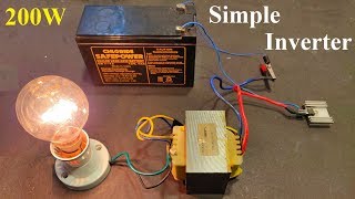 HD
HD HD
HD HD
HD HD
HD HD
HD HD
HD HD
HD HD
HD HD
HD HD
HD HD
HD HD
HD HD
HD HD
HD HD
HD HD
HD HD
HD HD
HD HD
HD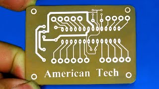 HD
HD