How to control direction of motor using RF transmitter and receiver circuit by electronics projects HD
How to control direction of motor using RF transmitter and receiver circuit by electronics projects RF controlled robot is controlled by using Four push button placed at transmitter side. Here we only need to push the buttons to control the robot. A transmitting device is used in your hand which also contains a RF Transmitter and a RF Encoder. This transmitter part will transmit command to robot so that it can do the required task like moving forward, reverse, turning left, turning right and stop. All these tasks will perform by using four push buttons that are placed on RF transmitter. Required Components DC Motor - 2 HT12D - 1 HT12E - 1 RF Pair - 1 Motor Driver L293D - 1 9 Volt Battery - 3 Battery Connector - 3 Connecting wires Robot Chasis - 1 7805 - 2 750K resistor - 1 33K resistor - 1 1K Resistor - 1 PCB L293D Motor Driver L293D is a motor driver IC which has two channels for driving two motors. L293D has Two inbuilt Transistor Darlington pair for current amplification and an separate power supply pin for giving external supply for motors. RF Transmitter and Receiver This is a ASK Hybrid Transmitter and receiver module operates at 433Mhz frequency. This module has a crystal stabilized oscillator for maintain accurate frequency control for best range. There we have to need only one antenna externally for this module. RF Transmitter Features: Frequency Range: 433 Mhz Output Power: 4-16dBm Input supply: 3 to 12 volt dc RF Receiver Features: Sensitivity: -105dBm IF Frequency : 1MHz Low Power Consumption Current 3.5 mA Supply voltage: 5 volt This Module is very cost efficient where long range RF communication is required. This module does not send data using UART communication of PC or microcontroller directly because there is lots of noise at this frequency and its Analog technology. We can use this module with the help of encoder and decoder ICs which extract data from the noise. The range of transmitter is about 100 meters at maximum supply voltage and for 5 volt the range of transmitter is about 50-60 meter with using a simple wire of single code 17cm length antenna. Pin Description of RF Tx GND - Ground supply Data In - This pin accept serial data from encoder Vcc - +5 Volt should be connect to this pin Antenna - A wrapped connect to this pin for proper transmission of data Pin Description of RF Rx GND - Ground Data In - This pin give output serial data to Decoder Data In - This pin give output serial data to Decoder Vcc - +5 Volt should be connect to this pin Vcc - +5 Volt should be connect to this pin GND - Ground GND - Ground Antenna - A wrapped connect to this pin for proper Reception of data http://www.youtube.com/c/electronicsprojects3 http://www.facebook.com/projects012 http://m.twitter.com/electronicspro3 https://plus.google.com/u/0/+ElectronicsProjects3 subscribe my channel for more videos
 HD
HD HD
HD HD
HD HD
HD
 HD
HD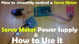 HD
HD HD
HD HD
HD HD
HD HD
HD HD
HD HD
HD HD
HD HD
HD HD
HD HD
HD HD
HD HD
HD HD
HD HD
HD HD
HD HD
HD HD
HD![[New] Top 3 Electronic Projects 2021](https://i.ytimg.com/vi/P6lKpZwLJfU/mqdefault.jpg) HD
HD HD
HD HD
HD HD
HD HD
HD