Piping Layout Using AutoCAD Plant 3D HD
With AutoCAD Plant 3D you can create 3D plant models using parametric equipment with project-specific piping specifications in order to produce the necessary documentation for all aspects of Water/Waste Water projects. Author Name: Andrew Manze Products used: AutoCAD Plant 3D, Inventor, Revit Follow us on Twitter: @AutodeskCivil3D Follow us on Facebook: https://autode.sk/2V66NZH Subscribe to the Blog to stay up to date: https://autode.sk/2BZSjUt Script: In this example, our pumping station will be housed in an industrial building modeled in Revit. Once our model has been transferred to plant3d for use as a reference we can commence modeling the associated steel and concrete structures. Once the pump supports have been modeled, the pumps can be defined using the builtin parametric equipment library. However, it is also possible to model custom equipment using inventor specifying the pipe connector positions and specifications and then exporting for use in plant3d. The inventor equipment converter in plant3d facilitates the transfer of equipment modeled in inventor and once in position the usage and tagging of the equipment can be specified adding the appropriate data to the new part. When the pump arrangement is complete it can be easily replicated readily for the piping phase. The P&ID is the schematic plan for the piping arrangement and can be referenced at any time during equipment and pipework modeling. In the 3d model, we can add piping directly using the available pipe modeling tools or alternatively by accessing parts from the line list which automatically transfers the piping specification and catalog from the P&ID database. Pipe connection parts such as mating flanges and reducing tees are handled automatically. Additional piping parts such as valves also can be drawn down from the database via selection from the line list and can be modified at any time as in this case changing the valve actuator from level to handwheel type. As well as allowing the use of external custom components plant 3d contains a comprehensive library of ancillary items to facilitate the completion of the pipework arrangement such as pipe hangers and clamps. These can be taken from the parts library and then modified to suit using the property panel. piping isometrics can be created automatically allowing piping to be checked and the configuration passed on to piping fabricators. Finally, piping orthographic drawings can be produced. The paper check provides validation of the drawing scales before the drawing is created. The generated views are then assembled onto the drawing sheet where bills of material can also be automatically generated from the database. The completed piping model can be validated in plant 3d and then combined with the Revit building model in order to produce further drawing and schedule documentation. The 3d model can also be explored in Navisworks in order to perform and manage the resolution of clash detection
Похожие видео
 HD
HD HD
HD HD
HD HD
HD HD
HD HD
HD HD
HD HD
HD HD
HD HD
HD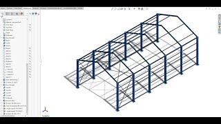 HD
HD HD
HD HD
HD HD
HD HD
HD HD
HD HD
HD
 HD
HD HD
HD HD
HD HD
HD HD
HD HD
HD HD
HD HD
HD HD
HD HD
HD HD
HD HD
HD![❔ Super Mario 3D World: 4-Mystery House Mad Dash (100 % All 10 Stars) [Gameplay Walkthrough]](https://i.ytimg.com/vi/P35uw97e7k8/mqdefault.jpg) HD
HD HD
HDПоказать еще